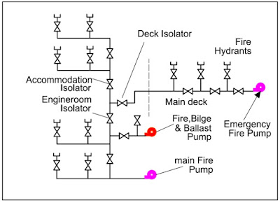
Below you can see a basic line diagram of fire main
Components> Main Fire pump: The main fire pumps located in the engine room at bottom platform, electrically driven prime movers. Normally a connection is given to the general service line from these pumps.
> Emergency fire pump: It is situated outside the engine room and supplied from emergency switch board or having independent prime movers.
> Fire hydrant: Fire hydrant is a connection point by which firefighters can tap into a water supply.
> Isolation valves: Isolation valves are provided to isolate the accommodation, deck or engine room fire lines in case of rupture of any of these sections. Located in easily accessible place deck.
> Relief valves: These valves are provided to prevent excessive pressure in any part of the fire main system.
> Drain valves: Drain valve is fitted to drain the fire line when not in use & also prevent the damage to pipe due to icing, while V/L is operating in Sub-zero temperature area.
